
For FDM printing there are four infill options that can be selected by the printer slicing software which change the infill construction of the part. So we have put together FDM design guides.
Unlike other printing technologies, which require the CAD file with the internal structures created as part of the design, with FDM printing a solid block can be printed with different infill options and without the need to modify the CAD file.
This allows the construction of the part to be adjusted to suit the end application. Material can be removed from the part via the printing process to lighten the part or reduce material usage and print time, thus reducing the overall cost of the part.
For FDM printing it is typical for parts, especially larger models, not to be printed with a solid infill – opting instead for a less dense option in order to reduce cost.
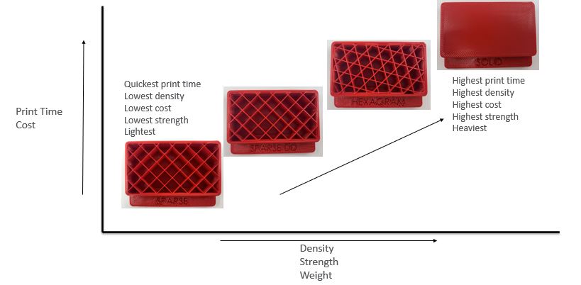
The 4 infill options available are: Solid, Hexagram, Sparse Double Dense and Sparse.
FDM Construction
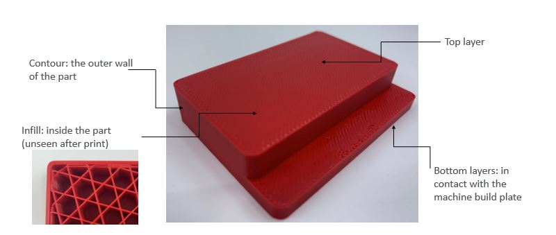
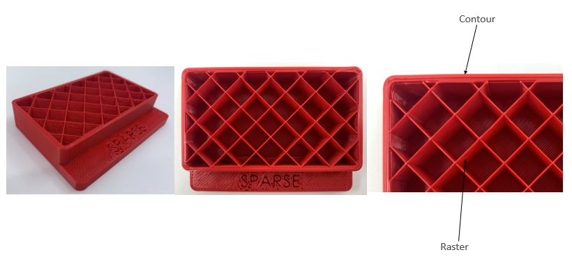
FDM printing uses an extrusion process to manufacture parts layer by layer. The printing tip creates an outside profile first, typically called a ‘contour’, and then creates the infill selected by the user, known as the ‘raster’. The raster pattern is typically laid at 45 degrees to the contour to give better part strength, and can be modified by the manufacturer to suit the application. The print has bottom and top layers which are similar to the contour in the way they contain the infill (which is not visible after print). An FDM part is constructed of 4 main sections, demonstrated in the graph below.
Porosity/Density
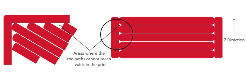
FDM parts are always porous, even the solid infill option is never 100% dense. The reason for this is the way the FDM printer constructs the parts. As with other traditional machines, toolpaths are created in order to control the movement of the machine and, in the case of an FDM system, the movement of the printing tips.
Geometries such as corners, where the toolpath is required to print in small areas, make it very difficult for the toolpaths to print right into the tight geometry, resulting in small voids in the print. The layering process via round filament also means that there are voids in the layering process in the Z direction, resulting in a porous part.
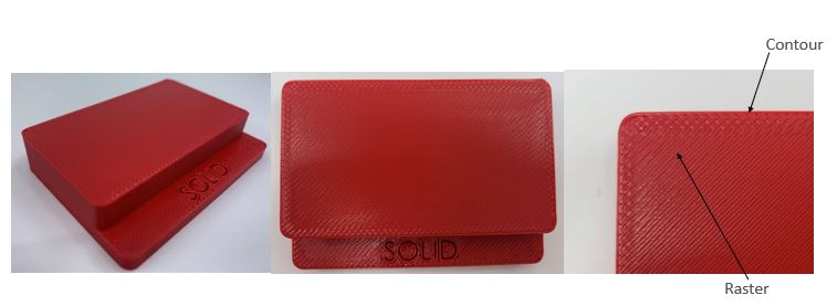
Solid Infill
As the name suggest the infill of the part is solid. An FDM part is never 100% solid due to the manufacturing process, where toolpaths are created by the machine for the heated tip to follow. Due to the size of the tip it is impossible to fill all of the areas of the part, leaving tiny pockets.
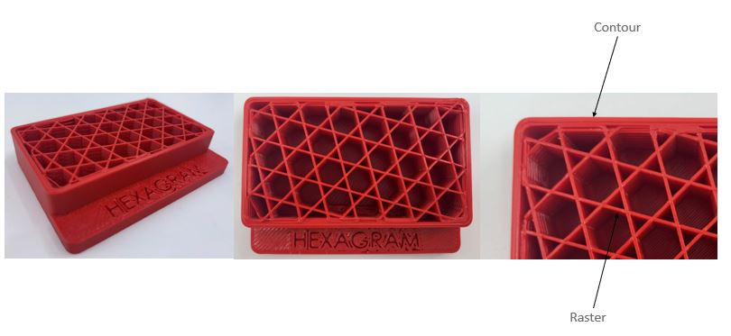
Hexagram
The infill is in the shape of hexagons.
Sparse Double Dense
The infill is a cross hatch on every layer.

Sparse
The infill is a cross hatch on alternate layers.
FDM Infill Matrix
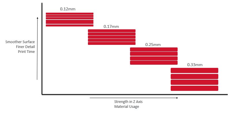
FDM Layer Thickness
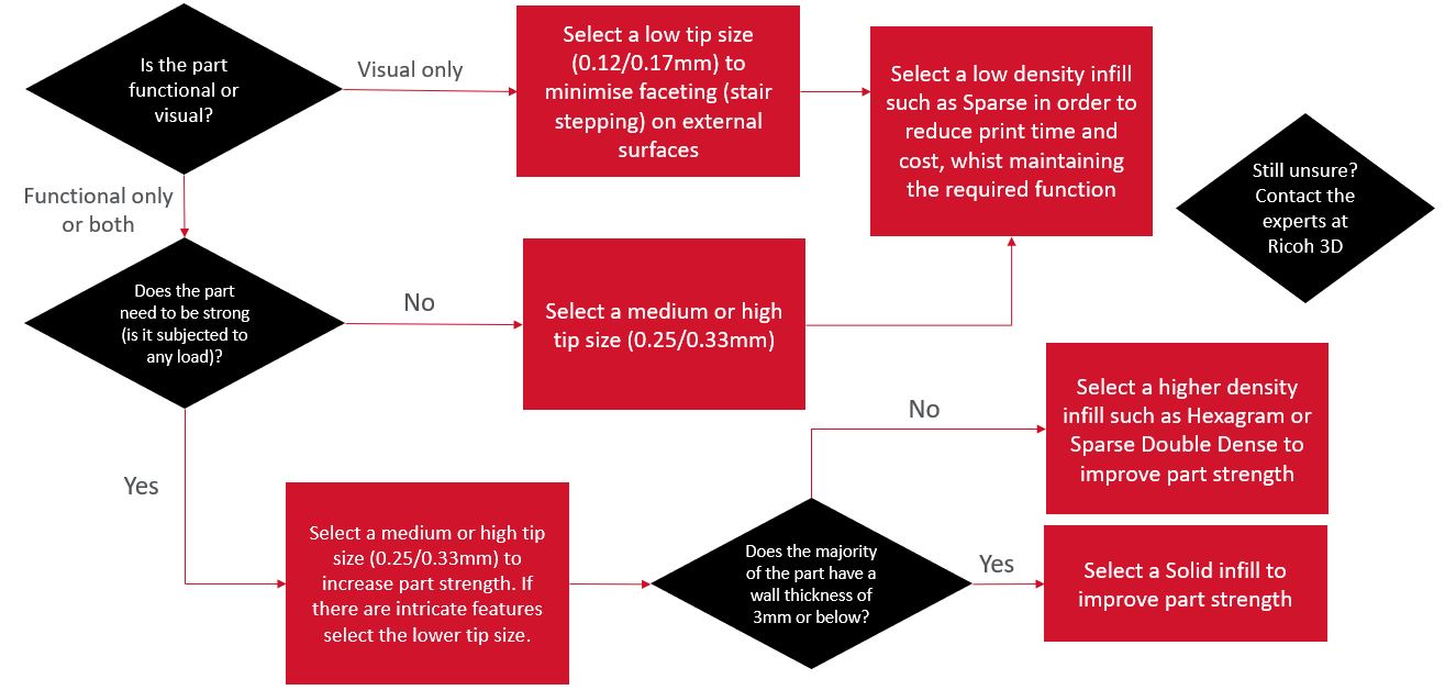
FDM Selection Guide
As every application is different it is difficult to create a ‘one fits all’ guide. However there are a few simple checks and decisions that can be made to help select the best infill and layer thickness for FDM printing.
Want to find out more about FDM design guides, contact our 3D printing experts today.