3D printing may seem like a minefield – but it doesn’t have to be.
Each 3D printer and technology has different printing capabilities, and there are common features that are used in the industry to test these. The team at Ricoh 3D use a number of well-documented scenarios to recommend key considerations at the design phase.
Follow our simple 3D Print Design Guide to help select the best materials and techniques for your project.
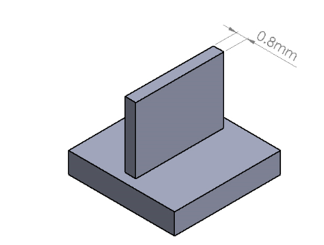
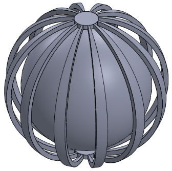
Minimum Feature Size
This is the minimum size that we can guarantee the system will be able to print. Any features under this size may not be reproduced by the printer.
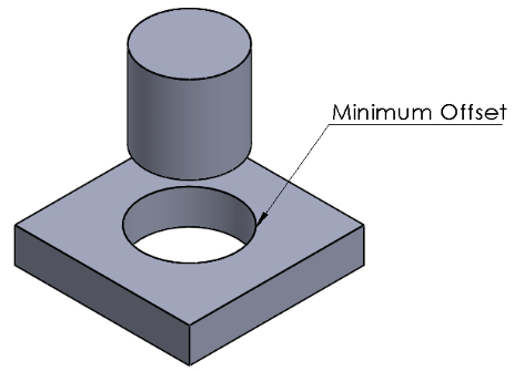
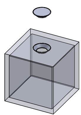
Offsets & Moving Parts
This is the minimum distance required between multi-body parts to achieve a clearance fit, allowing the free movement of parts. Any features under this value may end up being produced as one part or feature, and may not function as intended.
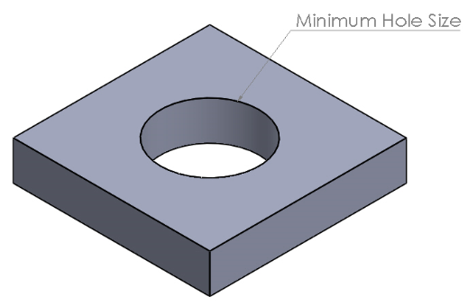
Holes
This is the minimum size required for the printer to reproduce a clean hole.
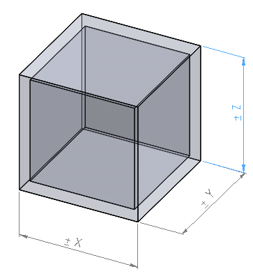
Tolerances
This is the accepted tolerance for each technology that has to be considered during the design phase.