Senior Design Engineer at Ricoh 3D, Richard Minifie, shares his thoughts on the evolution of design for 3D printing, the tools available today and what is still needed to unlock its full potential.
In my view, the most critical part of the additive manufacturing or 3D printing journey is right at the beginning, at the design stage. If 3D printing is not considered or understood early enough, then the benefits of this game-changing technology can never be fully exploited. I am a Design Engineer by the way, so perhaps I am biased!
There are two key areas when we talk about the important role of design in the 3D printing process. The first key area or stage is essential – the ability to design parts for the additive manufacturing process (DfAM). The second, often overlooked or misunderstood area, is how this design phase can unleash the full benefits of 3D printing; in my opinion one of the key hurdles the AM industry still needs to overcome.
Design for Additive Manufacture (DfAM)
The DFM stage is critical because, without its consideration, it would often not be possible for the technology to manufacture what has been conceived by the designer. The DFM process is familiar to all designers who develop products for manufacture. Typically, a designer will model around a process that they are familiar with, have access to and one which makes financial sense. In this way, the DFM stage becomes second nature to any designer.
When we talk about DFM for traditional, more established manufacturing processes such as injection moulding, considerations like uniform wall thicknesses and draft angles, amongst others, all apply. DFM rules can be complex and very restrictive in turning a concept into reality, thus dictating the overall design. With 3D printing there are DFM rules, some of which are generic across the ever-increasing range of technologies and some of which, such as minimum feature size, that are unique to different technologies and systems. In the AM industry we refer to this as Design for Additive Manufacturing (DfAM). Whilst there are DFM rules for AM they are far less restrictive than other technologies and therefore tend not to dictate the overall design concept.
There is a whole host of literature available online that discusses the DfAM rules, including Ricoh 3D’s own range of best practice guides to aid design for specific technologies. However, the benefits of 3D printing go well beyond this level of understanding. Designing products in a way that only considers the DfAM rules to ensure printability does not exploit 3D printing to its full advantage and does not create parts that couldn’t be manufactured any other way. This is where the true value of 3D printing lies, in my opinion superseding all of the other well publicised benefits such as speed, low volume manufacture and so on.
Quite simply, the DfAM design approach falls short of leading to innovative 3D printed designs. This is where “the creative needs to start getting creative” and is the second key area that I want to focus on here.
Design Software
But what does this all mean in practical terms?
First of all, as we know, in order to 3D print something we need a data file. This data file (typically an STL file) is created via CAD software. There are a number of CAD tools available on the market today but the majority of them work in the same way.
- Parametric Modelling captures the users design intent using features such protrusions and cuts that are defined and constrained, often using mathematical relationships between features to maintain geometry.
- Direct Modelling or Sub Divisional Modelling is a way of defining the critical geometries of a design, without any need to define and constrain geometry. It is a technique often likened to working with clay.
Popular CAD packages that are well established in industry are typically designed to work in the parametric modelling format. We as designers are used to modelling parts in this way: making sure everything is defined and constrained, and that every part of the geometry has been designed with intent. This mindset quickly becomes second nature during the design phase and so is very difficult to move away from. Even when the new freedom of 3D printing is understood, it often isn’t easy to translate into CAD due to the parametric modelling mindset and the structure of popular CAD packages which often obstruct the creative process.
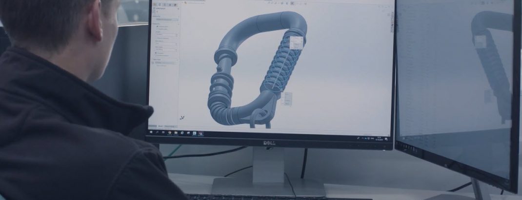
Take the CAD package that I use regularly, SOLIDWORKS, for example. As soon as I create a sketch, no matter how weird and wonderful the shape is, as soon as I exit the sketch to the next command I am prompted to either protrude that sketch or use the sketch as a cut, usually along a straight path. If I decide to create something with lots of undefined curved features the methods in those CAD packages can often be labour intensive, making the design process a long and laborious one and even the best conceived concept difficult to translate into CAD. This ultimately results in a compromised design. There are also limitations in parametric modelling when it comes to editing parts, as often changing defined geometry leads to a break in the model file which can be lengthy to resolve.
CAD creators have not just stood still while the 3D printing industry has evolved though. They recognise that 3D printing is becoming a serious manufacturing solution that CAD users want to take advantage of, and that the tools need to encourage and enable its use. Recent years have seen the emergence of 3D printing add-on functions being integrated into mainstream CAD packages. These enhanced packages range from DfAM to creative to print preparation tools, which make it possible to print directly to some popular hardware. SOLIDWORKS, for example, introduced the 3DEXPERIENCE platform and the concept of Sub Divisional Modelling using cloud-based application xShape within the ‘3D Sculptor’ module.
As the SOLIDWORKS tutorial explains above, this software offers the freedom to create non-defined geometry and does encourage the design of free form and organic shapes that would be difficult to design parametrically. Shapes are created and manipulated in 3 axes using loops and points to define the shape by eye, without geometry constraints. This allows the user to select shapes purely on visual appearance, rather than defining curved features to the nearest decimal point.
3DXpert, which is a collaboration between SOLIDWORKS and 3D Systems, brings together some of the features from 3D printing machine software such as orientation, build position and support generation. Interestingly, 3DXpert does include some basic optimisation tools too – such as the ability to create lattice structures to defined geometry – but this is the only feature that I would describe as a design aid. For me 3DXpert focusses more on preparing the part for print, than being a design tool.
Using the 3DEXPERIENCE suite of add-ons together with 3DXpert has its benefits but does make the process a little ‘clunky’ for me. Firstly, the geometry or reference geometry has to be conceived in SOLIDWORKS via parametric modelling, and then modified via either of the add-ons instead of being adapted during the design process. It does interrupt the flow of design and gives the feel that 3D optimisation is done as an after-thought.
The same is true of other software which sits alongside established CAD packages such as nTopology, where the design is first created and then modified to create the organic or lattice-like structures. Again, this is not designing for AM during the design phase, it is a process performed after the creation of defined geometry.
With some add-ons there is a focus on the DfAM and manufacturing process tools, instead of the features that will encourage innovative design. These tools are used further downstream in the manufacturing process, often by trained Process or Production Engineers via dedicated software designed to work with the printing systems. Whilst they are useful and do play an important role in 3D printing, are they really relevant to designers devising parts that will ultimately be produced using industrial printers?
To my mind this is an area where CAD system creators need to innovate in order to make the tools simple to use, all in one place, and workable in the design phase by seamlessly combining direct modelling with the parametric process – not afterwards as an optimisation stage, and not in expensive software add-ons. So long as these tools are still positioned as afterthoughts, widespread adoption and understanding of 3D printing is some way off.
The Design Mindset
What we have established so far is that there is more work to be done in unlocking the full range of benefits of 3D printing at the design phase. For some designers, and this is where I position myself today, although our intention when using CAD is to create organic designs, the tools that we use do not encourage this mindset and so we typically revert back to the way we have always designed parts, with small hints of 3D printing freedoms in the resulting concept. Software is not yet comprehensive enough to provide all the tools required in one place to create the shapes we desire, and so today additional complementary software is still a must.
There is the argument that organic and intricate shapes do not always add value, that we design them now for 3D printing simply because now we can. Ultimately as an engineer we always want there to be benefit in terms of performance, weight and cost reduction to truly maximise the power of additive manufacturing, instead of reducing it to a gimmicky tool for creating, nice aesthetic shapes with no real functionality.
It’s worth mentioning that of course it takes time to “unlearn” conventional design principles and habits. After all, we are engineers – we like uniformity and order. We are often guilty of over-engineering solutions and may even have a natural distrust for organic, sweeping, weird and wonderful geometries which means we overlook the techniques and tools available today. Some of these tools can not only produce these structures but also prove, via Finite Element Analysis (FEA) analysis, that the resultant geometry will perform to the intended use function and satisfy the engineer in us! Generative design or topology optimisation is one really interesting area of development…
Generative Design
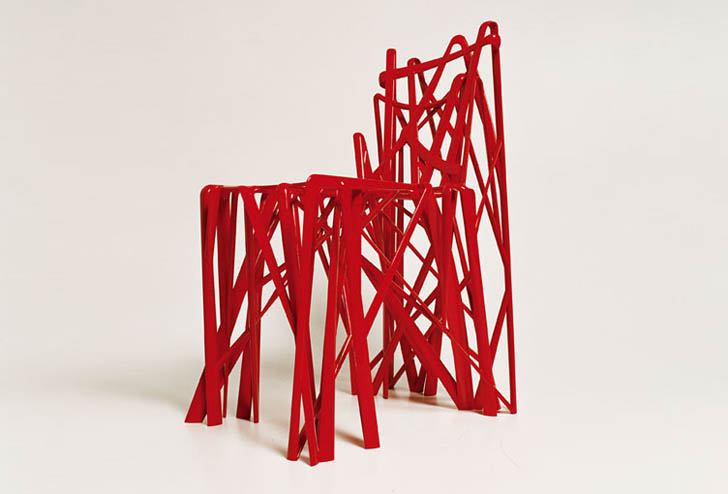
Generative Design uses FEA analysis to create a number of designs using the least amount of material possible. This leads to organic shapes that are virtually impossible to conceive or create in CAD, with the added reassurance from data that the parts will perform to the intended function. You could argue that this process removes creativity, as the software defines the shapes which we select based on the inputted data and geometry requirements. Some of the weird and wonderful shapes we associate with 3D printing are in fact not designed at all, they are conceived via intelligent software algorithms. Take this fascinating and innovative chair design, was it imagined or is it the brainchild of generative design?
Generative design and shape optimisation are performed via specialist software such as Autodesk’s Fusion 360, nTopology, Altair Inspire and SOLIDWORKS’ 3DEXPERIENCE platform. Typically, a basic concept exists which is then optimised. Critical areas, such as mounting points, are defined and the user can select the maximum area that the shape is to occupy. Loads, vibration, heat, fluid and any other physical effects are identified. The software then generates a series of concepts which can be selected by the user based on considerations like factor of safety or material usage, with the assurance that the selected design will perform as intended when manufactured.
To some degree this is making the design process much simpler and somewhat de-skilling it, but there’s no doubting that generative design is a powerful tool in creating innovative, organic and free-form shapes that can only be manufactured via 3D printing, with the all-important confirmation that the part will perform once optimised. For widespread adoption of generative designed 3D parts the tools need to be integrated into mainstream CAD systems though as part of the design process, rather than as an add-on enacted on a pre-designed part.
As a real-life case in Ricoh’s own manufacturing sites, internal tooling is extremely cost sensitive and subject to Ricoh’s “super low cost manufacturing” principle. To achieve a significant cost reduction on toner bottling tooling, without sacrificing Ricoh’s manufacturing standards, demanded the performance guarantees possible with generative design software. In this scenario, the known load and weight factors of toner bottle conveyancing were applied to FEA analysis to generate the least amount of material and cost possible, while building in a 4 X Factor of Safety. The resulting toner bottle jig design delivered a 94% weight reduction on the original CNC machined version, a 56% cost reduction and an increased production yield from 80% to 99.3% thanks to the reduced changeover time and energy savings. With 25,000 filled toner bottles distributed every day from our UK site alone, these savings are significant.
Understanding the process that you are designing for is a critical part of the design phase, and is especially true of the additive manufacturing process. It’s typical for companies to place designers on the ‘shop floor’ for a period of time to get hands-on manufacturing experience and the knowledge required to design products ready for production. This is something which certainly happens with Ricoh’s own apprentice programme. I can remember many years back to my first days designing jigs and fixtures for production lines; taking my design to the toolshop only to be taken down a peg by senior toolmakers for designing something that was impossible to manufacture was all part and parcel of the learning process! The emergence of additive manufacturing has involved a period of “unlearning” these established principles and practices for many engineers such as myself. It is designers who have no understanding of other manufacturing processes that may best utilise this technology and do not revert to old habits – people like students or earnest apprentices like me all those years ago! Students entering the engineering sphere now are able to design for AM straight from scratch, so learn early on to utilise the best technology for the product, rather than design for a pre-defined process. A lot of what I know today comes from trial and error. The next generation of engineers will have the benefit of understanding the full range of individual technologies prior to designing parts.
Design rules
So what are the DfAM rules that we need to know? It is difficult to describe what can and cannot be done with AM without referring back to the DFM rules for other technologies. What I don’t want to do is list off a whole plethora of DFM rules for other technologies that do not apply to 3D printing, although only doing this illustrates exactly what the technology is capable of. Instead, I have picked out some of the principles which tend to be the most restrictive below and how they relate to additive manufacturing.
Complexity
Complexity in 3D printing is pretty much free. As there is no associated tooling, we do not have to consider the manufacture of complex tools which can quickly become very expensive. When designing for injection moulding, for instance, it is known best practice to try and avoid undercuts, as this makes the tool complicated and therefore drives up the price. Simple open and close tools are favourable when parts are cost sensitive. Sometimes, however, undercuts cannot be avoided if the feature required is part of the overall function. This can tend to dictate the design process but can simply be disregarded with 3D printing.
Tolerance
One important thing to highlight here is the realistic tolerances we can expect from a 3D printed part today. Typically, an industry standard for Powder Bed Fusion 3D printing technologies is +/- 0.3% with a minimum tolerance of 0.3mm. This must be considered at the start of all projects where 3D printing is the assigned manufacturing process. Sometimes, where this tolerance is not acceptable, the 3D printed part can be post-machined to achieve the required tolerance. 3D printing has a far greater deviation than technologies such as CNC machining and injection moulding, which can often meet the tightest of tolerance requirements.
Some of the DFM considerations for three standard technologies that 3D printing is often benchmarked against are listed below.
Injection Moulding:
Consideration for material shrink rate, sink marks, ejection marks, gate location and gate witness, split lines, draft angles, uniform wall thickness, undercuts, sliding core witness marks, radii to edges, ribs, surface finish texture.
Vacuum Forming:
Draft angle, corner radii, draw ratio, undercuts, reference points, texture, post processing to add cutouts or ribs or join two parts together,
CNC Machining:
3 or 5 axis, work holding, consideration for cutters, pocket depth, rounded pocket corners, warpage when large amounts of material is removed.
Parts Consolidation
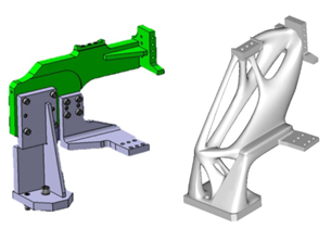
It is possible with AM to print parts in place, enabling the consolidation of multiple components into one file with moving features. Here, we have to understand the minimum offset of the intended print technology if parts are to move. Standard hardware fixings, like screws, that would assemble the components together at the end can be designed out of the overall assembly as the part is consolidated into one. This allows us to explore the further inherent benefits that 3D printing offers, such as reduction in assembly time and costs within the supply chain. This example from Fiat Automobile Group shows a welding assembly jig consolidated from at least nine specially manufactured components into one 3D printed part, without any additional fixings required.
AM also allows parts to be printed inside other parts, which is particularly interesting for those using the technology for innovative or aesthetic parts.
Customisation
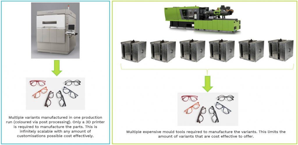
Customisation at scale has always been something of a manufacturing challenge, but this is not the case for 3D printing and is one of its most publicised advantages. Product design is completely opened up, as the number of part variations produced at any one time makes no difference to the printing process. To customise injection moulded components would require a range of different tools or removable inserts, which would be inefficient to run on a part-by-part basis for low volume applications.
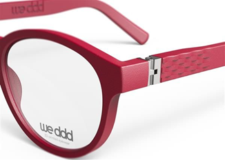
Eyewear is one industry already taking full advantage of customisation via 3D printing. Every face shape and visual capability is different so, in what is a highly individualistic market, eyewear tailored to each customer is increasingly expected. Eyewear brand Aoyama Optical France launched their We DDD eyewear collection in 2015 which takes advantage of the limitless design possibilities that 3D printing offers, with 14 frames available in multiple sizes, colour and textures.
“The We DDD collection is designed for the tech-savvy,
fashion-oriented consumer of today: aware of what they want and the high
quality they deserve. Standardized production and a one-size-fits-all approach
are no longer enough. We offer customizable options that speak directly to an
individual’s tastes and preferences. Aoyama’s goal with this collection was to
bring true mass customization to a luxury consumer-grade product.”
Philippe Beuscart, Aoyama CEO
To manufacture eyewear using injection moulding with all of the options and variants required would simply not be cost effective due to the multiple tool variants that would be necessary. Coupled with the agile nature of 3D printing and its ability to manufacture on demand, customisation on a mass scale is only possible via 3D technology.
Conclusion
In order to fully leverage the true end-to-end benefits of 3D printing it is essential, like most manufacturing technologies, that designers fully understand its capabilities. Design plays the most important role in the product development cycle for parts that are to be manufactured by 3D printing, simply because design influences so many of the other inherent benefits that AM has to offer. This is not only a case of knowing the DfAM rules, but of having a true understanding of the technology and specific system that is intended for manufacture, whether for a prototype or an end-use part. Having this knowledge of what the technology can and cannot do is essential before the design process starts.
But this in itself does not lead to the unhampered creativity which conceives objects only possible with 3D printing; the ability to translate this understanding into an innovative design is just as important. For this we of course need imagination, but we also need tools that interpret these ideas into CAD format; either via conventional parametric, direct/sub divisional modelling, via a combination or via generative design software.
What is clear is that 3D printing is a technology that is here to stay and that, when fully understood, is an incredibly powerful manufacturing tool to open up new ways of design thinking.