Background…
You can find printed circuit boards (PCBs) in almost any electronic device across industry. However, every device or object that uses a PCB requires its own unique version, with the design of the solder pallet needing to be exactly adjusted to accomodate the geometry of the printed circuit board.
Soldering pallets are used to apply through-hole components to printed circuit boards during assembly. They protect the Surface-Mount Technology (SMT) components in the circuits and expose the unmasked components to wave soldering at 200°C+ (392°f) heat. Most polymer materials melt under the harsh gaze of any standard soldering station.
When it comes to their manufacture, PCBs and the solder pallets that support their production have thermal, electrical, geometric and mechanical requirements that have tended to go beyond what most materials for 3D printing can offer.
What makes composite based additive manufacturing different?
Composite based additive manufacturing technology (CBAM) has been developed for all procedures within the PCB assembly process. It is the only powder-based process combining long-fibre fabrics of carbon or glass with high performance thermoplastic matrix materials like PA12 and PEEK.
The use of long-fibres (at least 12mm in length) offers significantly improved performance and strength, in comparison to short or chopped fibres, throughout the part and to the extremities, in addition to other properties like dimensional stability with heat and chemical resistance.
Thanks to its high temperature resistance and low coefficient of thermal expansion, PEEK is an ideal material for electronic manufacturing applications. The high-performance polymer enables the use of a soldering iron on the fixture without damaging it, holding the components in place during the process and eliminating issues with warping. With CBAM technology it is also possible to produce bespoke fixtures in just a few days and at a fraction of the cost compared to traditional manufacturing processes.
Ricoh 3D partnered with Impossible Objects in 2021 to bring their CBAM technology to the European market. Mark Dickin, Additive Manufacturing & Moulding Engineering Manager at Ricoh 3D said:
“Whilst many may not consider jigs and fixtures as the natural application for these types of composites, what we do know is that one of the main barriers to 3D printing is cost.
“The CBAM technology is a unique combination of cost efficiency and performance. We see long-fibre reinforced composties parts being used to up-engineer from lower cost plastics, lightweight metal parts or create entirely new parts that aren’t otherwise possible.”
Flat and feathered parts
Narrows parts such as circuit boards and propellers are great applications for CBAM technology. Printing point features and feathered edges with evenly distributed fibres to provide high strength and fully functional parts is possible thanks to the combination of long fibre sheets and high-performance polymer powders.
But how does it work?
It all starts by taking a sheet of non-woven fabric (made of either carbon fibres or glass fibres) and, using an inkjet printhead, the CAD slice is printed on the sheet using a proprietary fluid.
The sheet is then covered with a polymer powder which adheres where the fluid was deposited.
The excess polymer is removed, leaving the polymer selectively deposited on the sheet, with the steps repeated for all layers.
The sheets are then stacked, compressed and heated to the melting point of the polymer.
The fibres were there is no polymer are then sandblasted away to reveal the 3D printed part(s).
The unique process enables the production of parts with a high strength-to-weight ratio at up to half the cost of metal parts.
Read our case studies below to discover how CBAM is being used in the electronics manufacturing field…
Use Cases
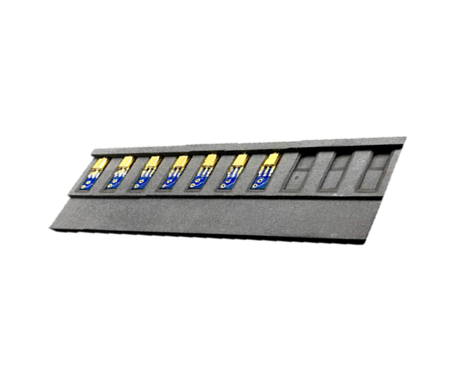
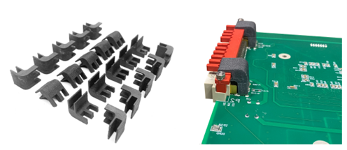
LED Alignment Tray
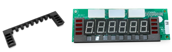
Part type: Carbon Fibre PEEK
Heat deflection temperature: 260C (500°F)
Chemical resistance: High
Outcome: Eliminated quality issues
Part dimensions: 103.0 x 29.6 x 10.5mm
Lead time: 1 week
The example here shows an alignment tray that was required to hold 16 LED lights perpendicular to the PCB board during the wave solder process for an electronics provider.
Originally, the customer wasn’t using any fixturing or methods to make sure the position of each LED was aligned for the next level assembly, but when their customer needed the LEDs to align with the display overlay that went over the PCB in the final assembly, they turned to 3D printing.
With 16 LEDs and 150 boards to rework, a jig was quickly developed using 3D printing that would hold the LEDs in place during the wave soldering process. However, PLA, ABS and PVDF fixtures all melted under the pre-heat of the wave solder and therefore Carbon Fibre PEEK was explored to produce a reusable high temperature alignment tray.
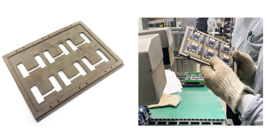
Soldering Fixture
Part type: Carbon Fibre PEEK
Heat deflection temperature: 260C (500°F)
Chemical resistance: High
Outcome: Tripled production; eliminated quality issues
Part dimensions: 109.9 x 34.9 x 10.9mm
Lead time: 1 week
When another customer received a 400% increase in orders, a fixture was needed that would batch the manual soldering process of a PCB soldered connector, in an effort to increase production and reduce failure rates.
The main failure area was in the terminal crimp to the shielded wire, which led the customer to redesign the cable/PCB assembly and convert the terminals to a PCB soldered connector.
Operations had to be quickly scaled up to accommodate the increased demand, but the bottleneck became the soldering of this new connector to the main board with a coaxial cable. The operators had to hold a board smaller than a postage stamp and make sure the connector was at 90 degrees on 3 axis, after pre-tinning the pads on 8,900 of these a week. After the first week the operators were complaining of hand cramps.
Consequently, a Carbon Fibre PEEK fixture was developed to hold 10 of the boards at a time while maintaining the position of the connector on the board.
The result? The customer tripled their output, with operators able to produce all 800 parts in 4 days, instead of three operators taking a week to do the same task.
Selective Soldering Fixture
Part type: Carbon Fibre PEEK
Heat deflection Temperature: 260C (500°F)
Chemical resistance: High
Outcome: Eliminated quality issues
Part dimensions: 152.5 x 101.6 x 15.5mm
Lead time: 1 week
When an aerospace customer returned 300 PCB assemblies due to a critical dimension they had missed, our customer prided themselves on providing an answer to a difficult question.
The PCB required a connector not visible in the image above, that needed to be elevated 0.7mm parallel off the PCB. The tolerance given was 0.1mm, which is near impossible to hold in an automated soldering process.
The customer was accustomed to creating its own tooling, so designed a geometry to solder nine connectors at a time in the process panel.
The new fixture, printed in Carbon Fibre PEEK, meant that the remaining panels could be reworked and passed all test for parallelism and height dimensions – with a further 300 ordered with no returns.
Surface Mount Heat Sink Tray
Part type: Carbon Fibre PEEK
Heat deflection temperature: 260C (500°F)
Chemical resistance: High
Outcome: Solved impossible problem
Part dimensions: 150.5 x 96.3 x 12.09mm
Lead time: 1 week
The fixture above was an experimental design for a customer exploring methods of dissipating the heat from the power transistor. The assembly, used in air traffic control radio equipment, is under continuous stress for 24-48 hours at a time and needs to be able to endure thermal stresses.
A non-metallic fixture was needed which would survive the extreme 265° temperature, as well as ensure the PCB soldered to the heat sink – counterintuitive for a piece of metal designed to dissipate heat.
This Carbon Fibre PEEK fixture made the process simple, as dowel pins could be used to hold the board and heat sink aligned in the 3D printed tray. This meant the fixture was confirmed in quantities of 25 per month for the next 5 years.
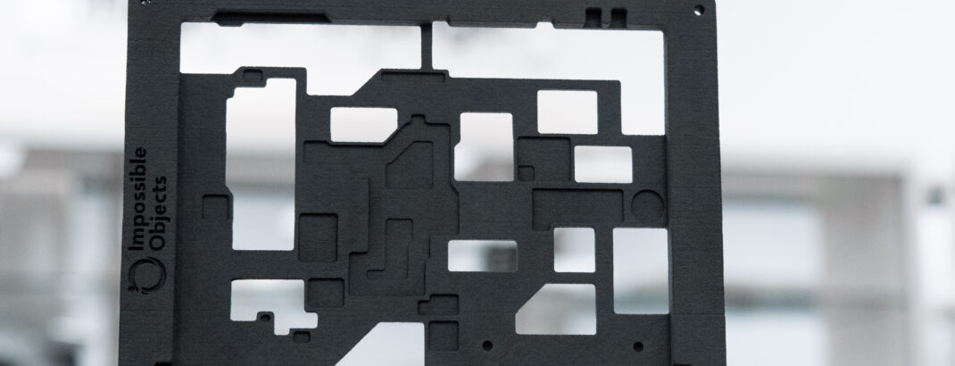
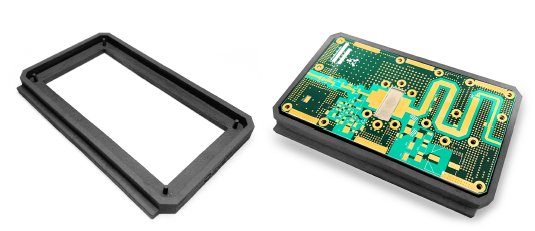
Wave Solder Pallet
Part type: Carbon Fibre PEEK
Heat deflection temperature: 260C (500°F)
Chemical resistance: High
Outcome: Met 2-week customer deadline
Part dimensions: 210.4 x 162.23 x 8.0mm
Lead time: 1 week
This Fibreglass PEEK wave solder pallet was designed and printed production-ready in under one week, allowing our customer to meet a two-week deadline.
Kapton tape had previously been used to cover the gold “fingers” of the board, which were plugged into a power supply and therefore needed to be clean of solder.
When the tape repeatedly fell off or was forgotten, a pallet was designed to prevent this issue from happening again. The expected lead time for a pallet was normally six weeks, with additional time for redesign.
With FibreGlass PEEK the first and second iteration had been produced in only two weeks, and tested successfully with a replacement panel.
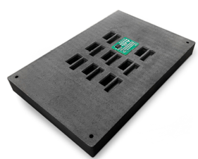
SMT Pallet
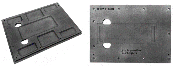
Part type: Carbon Fibre PEEK
Heat Deflection Temperature: 260C (500°F)
Chemical resistance: High
Outcome: Allowed production to begin 6 weeks faster than using a traditional manufacturing solution
Part dimensions: 254.0 x 177.8 x 6mm
Lead time: 1 week
Our customer had been producing SMT pallets for many years, reworking 20-30% of the board on every order after they had been tested, due to the fact the assembly could only be tested in the housing. Housing is ultrasonically welded around the PCB, meaning any failures result in the destruction and loss of the housing.
The leading cause of failures was the solder quality of a connector which was impossible to inspect by normal means to the hidden leads under the part. The connector would lift off a few pads due to warping during SMT re-flow.
To combat this, a Carbon Fibre PEEK SMT pallet was produced with a pocket for the connector. This improved yields to around 85-90% and with no further tweaking of the soldering process, the customer met its goal of a 95% first pass yield on this product.
Selective Soldering Fixture
Part type: Fibreglass PEEK
Heat deflection temperature: 260C (500°F)
Chemical resistance: High
Outcome: Quick high-volume turnaround
Part dimensions: 15.75 x 16.58 x 15.00mm
Lead time: 1 week
Maintaining the position of the connector in the selective soldering process caused issues, as whichever side was soldered first would inevitably cool down and lift the other side. The hardware could not be installed when soldering the connector since there were leads directly next to the hardware, and the screws and nuts needed to be free of solder.
Fibreglass PEEK fixtures now hold the connectors from leaning forwards or backwards during the soldering process. When the PCB cools the hardware is installed and left to right difference is eliminated by torquing the screws down.
Since this connector has 44 leads, rework is a full project that can take hours. The Fibreglass PEEK fixture has so far fixed the issue.
Conclusion
One of the challenges historically of working with composites in electronics manufacturing using conventional methods has always been time and cost.
Additive manufacturing is changing this, providing a faster and more efficient way to produce composite parts, whether it is by printing tooling or end-use parts directly.
It is no wonder that composite, fibre-reinforced materials are appealing to many industrial sectors. The materials are stronger and more durable than un-reinforced polymers and at the same time lighter and more affordable than metals.
At Ricoh 3D we are excited about the opportunities that composite AM provides and looking forward to developing applications with our customers that exploit the capabilities and performance achievable with CBAM technology – a unique powder-based composite manufacturing technology.